
“Arkwright! The management of the Stella and Corglass seemed puzzled. Did you convince them we could grow sugar cane in the back yard?”
By Peter JDK Dawes, Stella and Corglass Light Railway
Illustrated as a grey scale line drawing in “Fowler Locomotives in The Kingdom of Hawaii” by Jesse C Conde, Narrow Gauge Railway Society No 140.
I can find no photographs of this wagon, so I based the design based on 14” (18mm) wheels and worked out the dimensions from this. The size suits my railway and looks in proportion.
I originally made 4 sets of frames about 2012 to go with my Peter Angus Avonside geared locomotive. For various reasons – idleness, kidney failure and too many projects – I have built two. However, another has started and the final one has more than the frames. Kidney transplants are amazing!
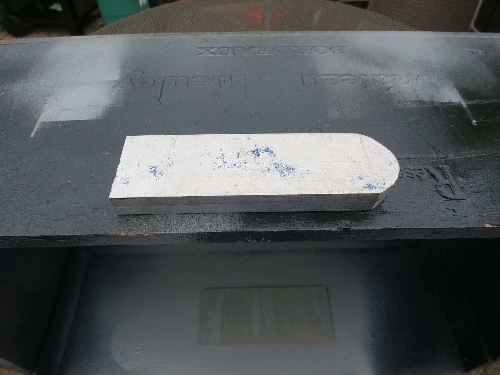
Aluminium former for the frames.
I decided/deduced that the length over buffers would be 218mm and the frame width would be 47mm. The radius of the Aluminium former is approximately 23mm or so. Two pieces of Tenmille G scale rail, about 250mm long, were annealed and bent round the former, and the long ends were cut to fit the required length. These were then silver soldered together and 1” x 1/8” x 40mm stretchers were fitted in between the webs of the rails. They are large enough to allow the bogie pivots to be positioned correctly later. (I changed to 1/2” brass later as that was in the box.)
To strengthen the joints, I used offcuts of code 200 bullhead rail, which conveniently fits in the web and as that was my track at the time there was an abundance of said offcuts. The advantage of silver soldering is that later soft soldering will not cause the frames to fall apart, and various soft solders can be used at each stage along with heat absorbing clamps as one goes. In my early 4mm scale scratch building I ended up with a full set of parts now and then. Drill three holes in the buffer beam 1.8mm. These will hold 1/16” rivets into the wood behind.
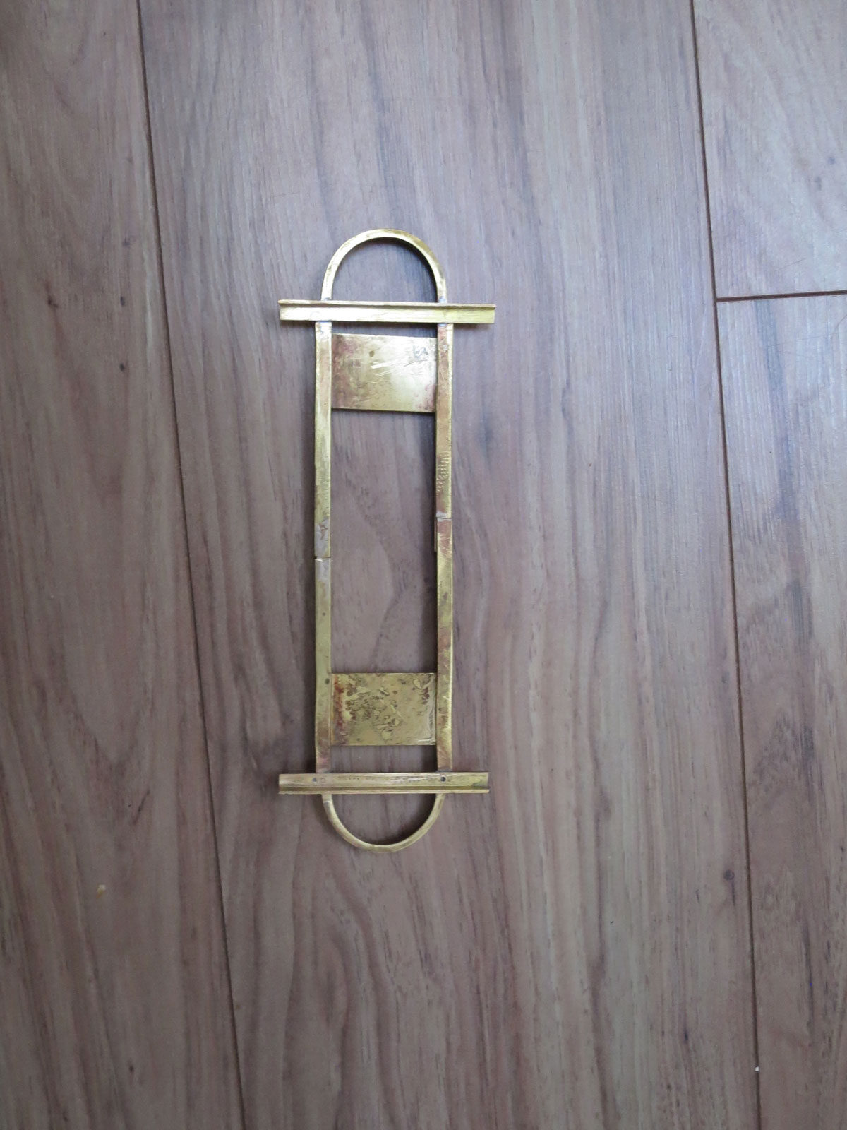
The frames, with cross members to hold the platform added.
I then filed the buffers to profile using a belt sander. The cross members that hold the wooden platform were added with high melting point solder. So far so good. I used 6x6mm angle or 1/4” angle. Using the latter one side will need to be made true, filing probably. These are 72mm long. I used 188 Celsius or higher solder.
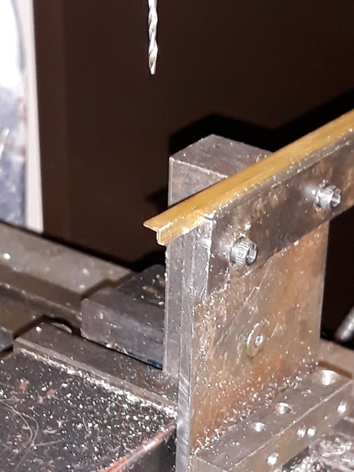
Drilling the angle
Next 4x4mm angle was prepared for the angled ends. Pieces 60mm long had a cut made at 50mm and the angle selected (by eye) soldered up using the 188 Celsius or higher solder to fix the piece. 3 holes 1.6 mm diameter at 12mm centres were drilled starting at 20mm from the base. Using a small vice in a vice on the mill drill allowed for accuracy. The angles were soldered using 188 C solder clamping with small steel spring clamps, a pain but worthwhile. The rods of 1.4mm brass and the central spacer cut from scrap then brass sheet were soldered up with detail solder (140 C). Finally, the small angle plates, more gash brass sheet were fitted. Gosh! I suspect you know all the above excuses were not the only reason mass production was slow.
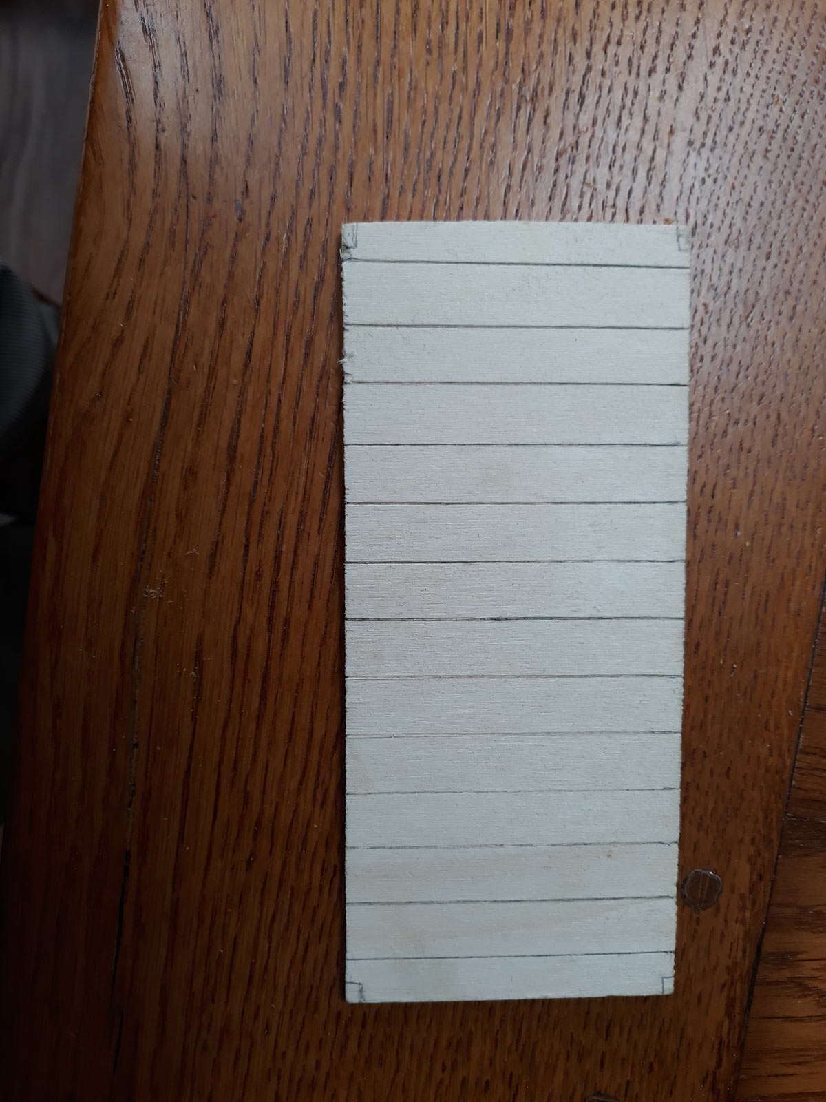
Preparing the wooden platform
Now the carpentry! 4mm ply from a model boat supplier was prepared, 162 x 72 mm. Score 12mm planks, using a corner of a screwdriver blade and a steel ruler, Atropos kit style. Start from the centre and work outwards. Slightly over long would allow adjustment. Make sure the grain is across the width, it looks better. Experience! Glue the wood to the 6x6mm angle, epoxy is what I use. At this point I would drill the bogie pivot holes at the same distance from the ends of the frames (50mm) either 6BA or 3mm tapping size. Then spray with etch primer, enough to remain wet while etching (it does not work dry I am told). Spray with grey primer and then spray or brush paint the frames black. Then when dry I use bauxite brushed liberally for the planking top. More than one coat may be needed. I think these were Victorian wagons and paint was used copiously, Leeds to Hawaii was a long way.
Finally, at least for the wagon superstructure, add the 1/8 x 1/8” or 3×3 mm square tube On the upper surface of the planking at the sides. Epoxy glue works well, but three sides will be needed to be etched primed first, easy the side on the bottom of the spray booth, work bench, cardboard box or whatever won’t get the spray. When all sound, paint black.
These wagons will not need added weight. One may prefer to paint the planking and frame separately and tidy up if necessary; this also works. The corners of the deck may need removing to fit between the fancy ends. The coupling hooks are held in a semi-circular block held by epoxy in the inside curve of the buffer, 5mm lime 10mm deep and filed to fit. The hooks are added at the end. Paint black or bauxite as you wish I have done both, not on the same wagon.
Bogies: I made my own, you might want to look for commercial ones. (My brother would be rude at this point, he is an ENT surgeon out in NZ.)
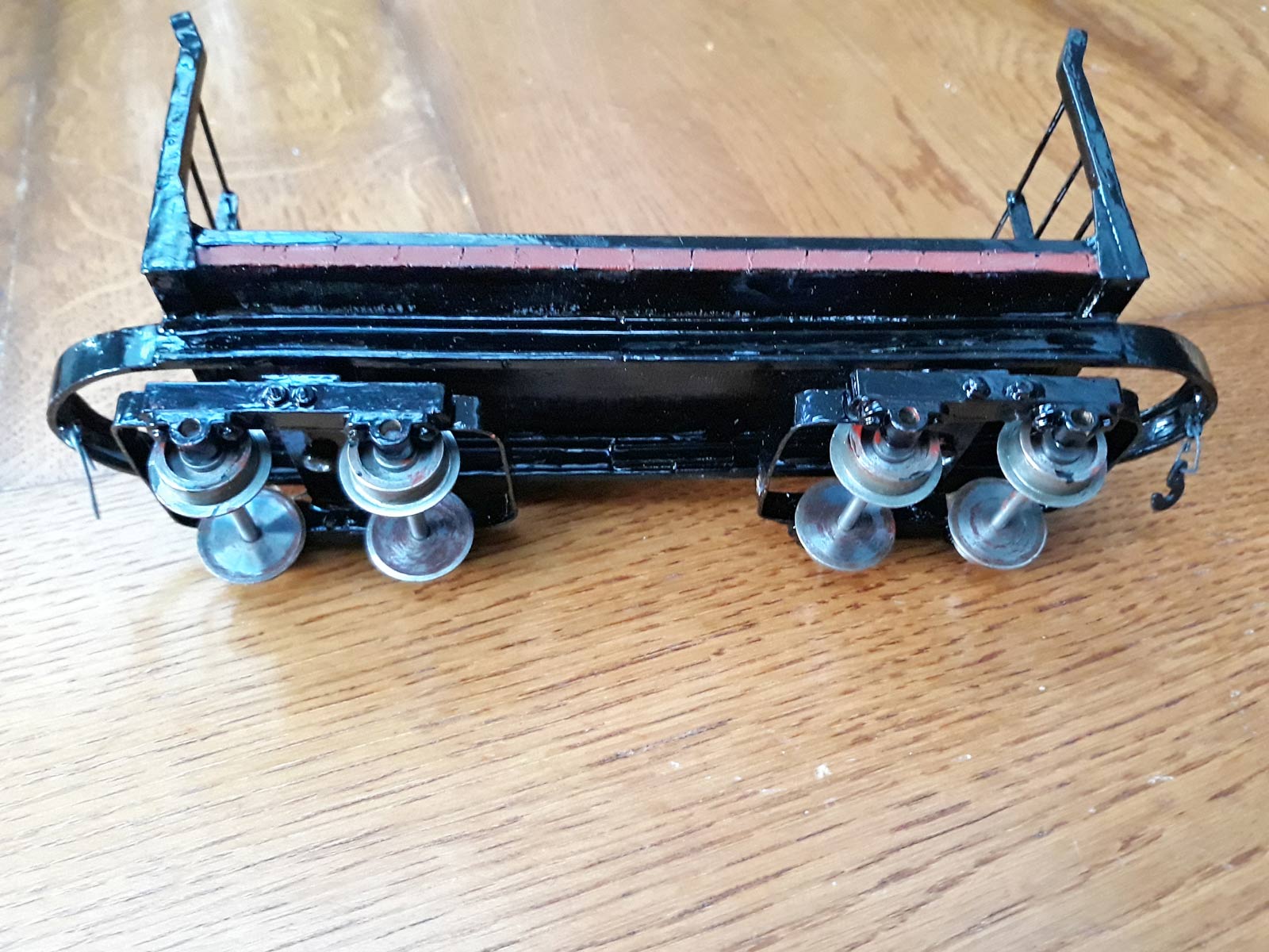
Underneath view showing the bogies
The stretcher is 1/2” x 1/8” brass, I used 47mm for the first 2 and soldered them to the 0.8mm by 1/4” (6mm) strip that is folded carefully to produce the curved ends and flat sides, with clearance for the wheels inside. Finally, it is soldered into the final shape clamped and then to the stretcher. Fiddly but quite strong. The axleboxes are pedestals from Essel Engineering added to 1/4 x 1/4 brass frames 45mm long.
The pedestals each take a pair of 10BA hex screws and I set each frame level in a milling drill on the mill drill and set the holes up using the DRO system I have. This ensures accuracy and they then are turned through 90 degrees and 2 10BA holes on the horizontal centre line are drilled about 2.5mm either side of the vertical centre line. These frames can be clamped to the bogie frame and 10 BA holes spotted through one side and then the other, so the axles are parallel. It may seem flimsy but they run well. I am about to try a different method that all this thinking and writing this has suggested. Finally, bearings of 1/2” to 3/4” round brass can be parted off at the height to produce the correct buffer height for the locos in use.
The pedestal axleboxes take 3mm journals and I first used IP engineering wheels. They will also take Brandbright 2mm journals with Slaters Plastikard axle bearings, retrieved from kits where they were not needed. Lots of possibilities exist.
I originally worked from rough sketches lost after the first wagon 7 years ago. The sketches and measurements were recreated from the prototype: reverse engineering.
I have enjoyed making these wagons though, as the caption at the top suggests, they are not what you expect on a British narrow gauge railway: imagine a sugar beet load!